

Beryllium copper fingerstock is widely used in EMI shielding applications because it combines electrical conductivity with excellent spring properties.
However, selecting the correct material is only the beginning.
A fingerstock gasket must also match the mechanical dimensions, compression requirements, mounting structure, and operating conditions of the enclosure.
A product with suitable material properties may still perform poorly if it is installed with insufficient contact pressure, excessive compression, or an unsuitable mounting method.
For this reason, fingerstock selection should begin with the mechanical interface and electrical requirements of the application.
This article explains the main engineering considerations when selecting and installing EMI fingerstock.
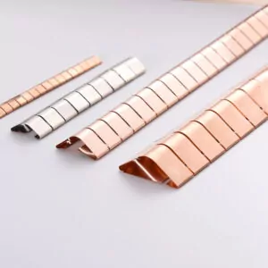
1. Start With the Gap Between the Two Conductive Surfaces
The first step is to understand the actual gap that the fingerstock must bridge.
In a shielded enclosure, the distance between a door and its frame may vary because of:
- Manufacturing tolerances
- Door alignment
- Hinge movement
- Panel flatness
- Thermal expansion
- Mechanical deformation
- Installation variations
The nominal gap shown on a drawing may not represent the minimum and maximum operating gaps.
Before selecting a profile, measure or calculate the full tolerance range.
The fingerstock must maintain contact at the largest gap while avoiding excessive deflection at the smallest gap.
This is particularly important for large shielded room doors, where small alignment differences can accumulate along the perimeter.
2. Understand Free Height and Working Height
Two important dimensions are the free height and working height of the fingerstock.
Free height is the height of the fingerstock before compression.
Working height is the remaining height after the mating surface has compressed the fingers.
The difference between these dimensions represents the deflection.
For a simplified calculation:
Deflection = Free Height − Working Height
Compression ratio can be expressed as:
Compression Ratio = Deflection ÷ Free Height × 100%
For example, if a fingerstock profile has a free height of 5 mm and is compressed by 1 mm, its compression ratio is 20%.
However, the allowable compression range is profile-specific.
Do not apply a universal compression percentage to every fingerstock design. Always use the manufacturer’s force-deflection data and recommended working range.
3. Why Excessive Compression Should Be Avoided
One common installation mistake is selecting a fingerstock profile that is too tall for the available space.
The fingers may then be compressed beyond their intended elastic working range.
This can lead to:
- Permanent deformation
- Reduced spring-back
- Increased contact force
- Difficult door operation
- Accelerated fatigue
- Mechanical damage
In shielding doors, excessive contact force can also place unnecessary stress on the door structure and hinges.
The correct profile should provide sufficient deflection to maintain contact without forcing the fingers into an over-compressed condition.
4. Why Insufficient Compression Is Also a Problem
Choosing a profile that is too short can be equally problematic.
If the fingerstock does not make consistent contact with the mating surface, electrical continuity may become unstable.
Possible consequences include:
- Intermittent contact
- Increased contact impedance
- Localized RF leakage
- Inconsistent shielding performance
- Sensitivity to vibration and door movement
The design must therefore consider both the maximum and minimum operating gaps.
A suitable fingerstock profile should remain within its recommended working range throughout the complete mechanical tolerance range.
5. Contact Force and Door Closing Force
Fingerstock generates a spring force when compressed.
This force helps maintain electrical contact, but it also increases the mechanical force required to close the door or panel.
For large shielded doors, the combined force from the entire fingerstock perimeter can become significant.
When selecting a profile, consider:
- Force per finger
- Number of contact fingers
- Total contact length
- Available door closing force
- Hinge and latch capacity
- Expected operating cycles
A profile with high contact force may not be suitable for a lightweight access panel.
Conversely, a heavy-duty shielding door may require a more mechanically robust contact configuration.
The objective is to achieve reliable electrical contact without creating unnecessary mechanical resistance.
6. Choose the Appropriate Surface Treatment
Surface treatment affects corrosion resistance, electrical contact, wear, and compatibility with the mating material.
Common options for beryllium copper fingerstock include:
Natural Finish
An unplated or natural finish may be suitable for certain applications where the mating materials and environmental conditions are compatible.
However, the surface condition and corrosion exposure should be evaluated.
Tin Plating
Tin plating is commonly considered for general electrical contact applications.
It can provide useful corrosion protection and compatibility with certain mating surfaces.
The actual performance depends on the coating quality and the materials in contact.
Nickel Plating
Nickel plating can improve wear and corrosion resistance in some environments.
However, contact resistance and electrical interface performance should be considered alongside durability.
Other Plating Options
Gold or silver finishes may be considered for specialized applications requiring particular contact characteristics.
These options should be discussed with the supplier according to the project requirements.
The most expensive plating is not automatically the best choice.
Material compatibility, environmental exposure, electrical requirements, and cost must all be evaluated together.
7. Consider Galvanic Corrosion
When two dissimilar metals are in electrical contact, galvanic corrosion may occur under suitable environmental conditions.
This is particularly relevant when fingerstock is mounted on aluminum structures.
The combination of base materials, plating, moisture, and surface contamination can influence corrosion behavior.
Before confirming the surface finish, consider:
- Fingerstock material
- Enclosure material
- Plating type
- Humidity
- Salt exposure
- Cleaning chemicals
- Expected service life
For outdoor or humid installations, material compatibility should be reviewed carefully.
A suitable plating system can help reduce corrosion risks, but it should not be treated as a substitute for proper environmental design.
8. Select the Correct Mounting Method
The mounting method affects installation time, mechanical retention, maintenance, and electrical continuity.
Noordin’s published fingerstock configurations include snap-on and 3M adhesive tape mounting options.
Snap-On Mounting
Snap-on designs attach to a supporting edge or designated mounting structure.
Advantages include:
- Convenient installation
- Mechanical retention
- Potentially easier replacement
- No need for adhesive curing
The supporting structure must match the fingerstock profile and dimensions.
Adhesive Tape Mounting
Adhesive-backed fingerstock can simplify installation on suitable surfaces.
It is useful when drilling or machining the enclosure is undesirable.
However, the mounting surface must be clean, dry, and compatible with the adhesive.
Temperature, humidity, surface condition, and long-term mechanical loading should also be considered.
Importantly, the adhesive should not be assumed to provide the required electrical bonding path. The conductive contact between the fingerstock and enclosure must be properly established.
9. Compression Contact vs. Wiping Contact
Fingerstock can operate in different mechanical arrangements.
Compression Contact
In a compression arrangement, the door or panel closes against the fingerstock.
The fingers deflect and maintain contact pressure while the surfaces remain closed.
This is common in cabinet doors and shielded enclosure covers.
Wiping Contact
In a wiping arrangement, one surface slides across the fingerstock during closing or movement.
This creates a wiping action along the contact surface.
It may help reduce the accumulation of light surface films, but it can also increase wear if the geometry or movement direction is unsuitable.
When designing a wiping interface, check:
- Sliding direction
- Finger orientation
- Contact travel
- Surface finish
- Friction
- Wear over repeated cycles
The fingerstock should be installed so that the fingers are not caught, bent backward, or damaged during movement.
10. Installation Practices for Shielded Doors
Shielded room doors require particular attention because the contact interface often extends around a large perimeter.
A reliable installation should consider:
Continuous contact: Avoid unintended gaps between separate fingerstock sections.
Corner treatment: Use suitable corner arrangements to maintain electrical continuity.
Even compression: Check that the door closes consistently along the entire contact line.
Mounting security: Ensure that the strip cannot move or detach during repeated operation.
Surface preparation: Remove unsuitable coatings or contamination from designated electrical contact areas according to the installation design.
Maintenance access: Allow worn fingerstock to be inspected and replaced without unnecessary structural modification.
After installation, check the door’s mechanical operation and electrical bonding.
11. Common Fingerstock Installation Mistakes
Several problems can reduce the effectiveness or service life of fingerstock.
Mistake 1: Selecting by Thickness Alone
Material thickness is only one part of the specification.
Profile height, finger geometry, spring force, and mounting dimensions are also important.
Mistake 2: Ignoring Door Tolerances
A profile that works at the nominal gap may lose contact when the door is slightly misaligned.
Always consider the worst-case operating gap.
Mistake 3: Over-Compressing the Fingers
Excessive compression can permanently deform the spring structure.
Follow the manufacturer’s recommended deflection range.
Mistake 4: Using an Incompatible Surface Finish
An unsuitable plating combination can increase corrosion risk or affect long-term electrical contact.
Mistake 5: Leaving Gaps at Corners
Poorly connected sections can create localized discontinuities in the shielding interface.
Mistake 6: Treating Fingerstock as an Environmental Seal
Fingerstock is primarily an electrical contact and EMI shielding component. It should not automatically be treated as a water, dust, or pressure seal.
If environmental sealing is required, a separate compatible sealing solution may be necessary.
Mistake 7: Ignoring Maintenance
Repeated operation, contamination, corrosion, and mechanical damage can affect contact performance.
Regular inspection is important for critical shielding interfaces.
12. A Practical Selection Checklist
Before ordering, confirm the following information.
| Parameter | Information Required |
|---|---|
| Material | Beryllium copper or specified alternative |
| Material thickness | Required strip thickness |
| Profile | Shape and contact geometry |
| Free height | Available installation height |
| Working height | Actual compressed height |
| Gap tolerance | Minimum and maximum gap |
| Contact force | Required mechanical contact force |
| Surface treatment | Natural, tin plated, nickel plated, etc. |
| Mounting | Snap-on, adhesive, or mechanical fixing |
| Operating conditions | Temperature, humidity, vibration |
| Operating cycles | Expected opening and closing frequency |
| Dimensions | Length, width, and installation details |
Providing this information helps the supplier recommend a more appropriate fingerstock configuration.
Conclusion
Selecting and installing EMI fingerstock correctly requires more than choosing a conductive material.
The mechanical gap, spring profile, compression range, contact force, surface treatment, mounting method, and operating environment all affect the final result.
For shielded doors, cabinets, and RF enclosures, the best design is one that maintains reliable electrical contact throughout normal mechanical operation without excessive compression or wear.
By checking these parameters before installation, engineers can improve shielding continuity and reduce the need for future maintenance.
📌 Explore Noordin Beryllium Copper Fingerstock:
https://www.emcnoordin.com/product-category/shielding-materials-and-components/fingerstock-shielding-materials-and-components/
Fore more information:
What Is EMI Fingerstock? Understanding Its Role in Electromagnetic Shielding

