
In modern power electronics, particularly in variable frequency drive (VFD) systems and other motor control applications, both line reactors and output filters play crucial roles in mitigating electrical noise, protecting components, and improving performance. Although they may seem similar in function, they serve distinct purposes and are installed at different points in the power circuit. Understanding the difference between these two components is essential for proper system design and effective EMI management.
What is a Line Reactor?
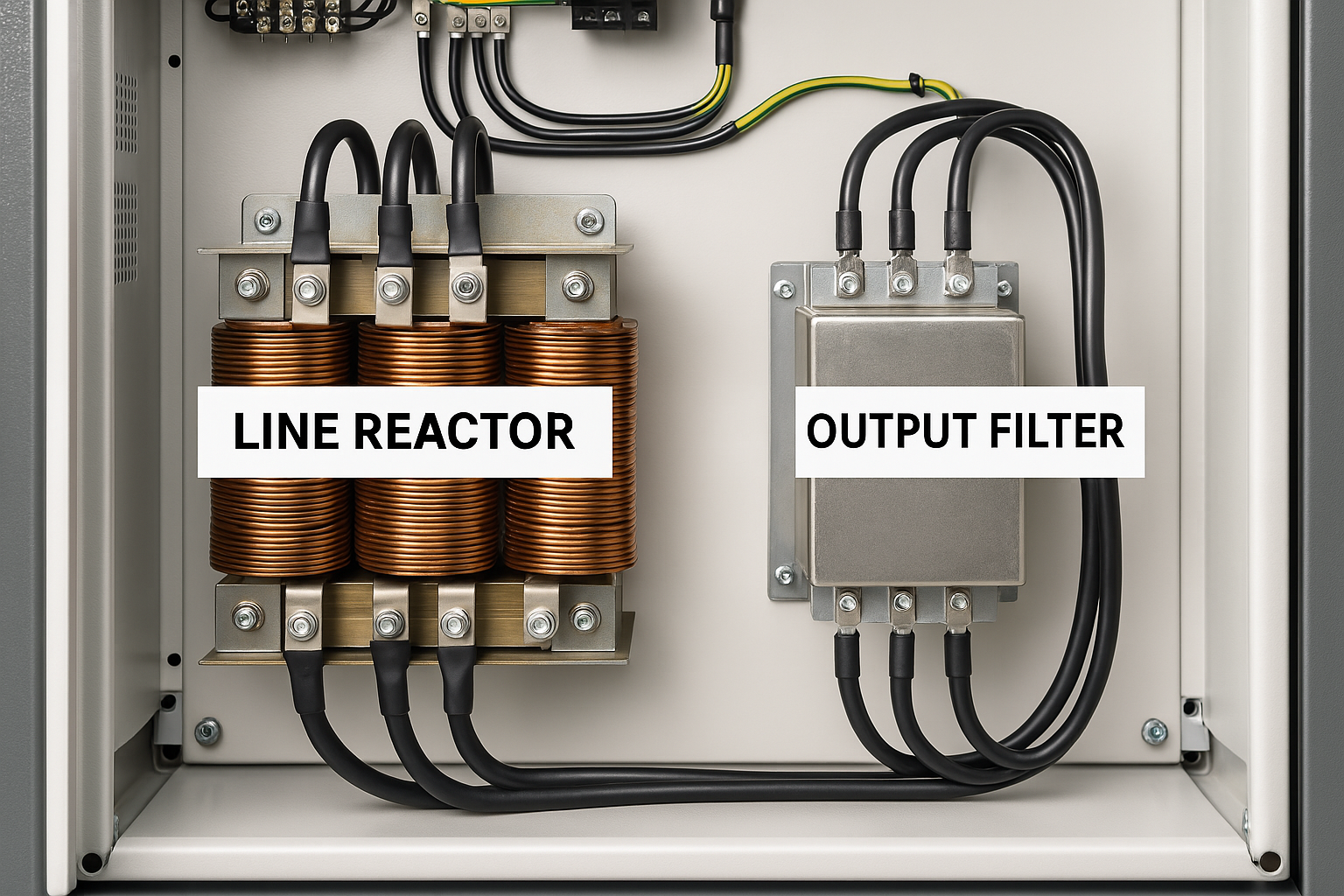
A line reactor is a type of inductor installed on the input side of a VFD or power converter. Its main function is to protect the drive and reduce electrical disturbances from the utility line.
Key Functions of Line Reactors:
-
Protects against voltage spikes: By adding impedance to the line, a line reactor can absorb and reduce transient overvoltages coming from the power grid.
-
Reduces harmonic distortion: Harmonics are unwanted high-frequency voltages or currents that can affect the performance of electronic equipment. Line reactors reduce harmonics created by VFDs.
-
Improves power factor: A reactor can help manage reactive power flow, slightly improving power factor in some systems.
-
Minimizes inrush current: The inductor limits the initial surge of current when the system starts.
Applications:
-
Industrial motor control systems
-
Power distribution panels
-
Input side of VFDs and inverters
-
Environments with unstable or noisy power supplies
What is an Output Filter?
An output filter is installed on the output side of a drive, between the VFD and the motor. Its primary role is to filter out high-frequency components and smooth the voltage waveform before it reaches the motor.
Key Functions of Output Filters:
-
Reduce dV/dt (voltage rise time): High switching frequencies from VFDs can cause steep voltage rise times that damage motor insulation over time. Output filters reduce this risk.
-
Minimize EMI/RFI emissions: Output filters suppress electromagnetic interference and radio frequency noise, especially important in sensitive or regulated environments.
-
Protect long motor cable runs: Long cables can act as antennas, radiating noise or creating voltage reflections. Output filters help mitigate these effects.
-
Extend motor lifespan: By delivering a cleaner sinewave-like output, output filters reduce mechanical stress and heating in motors.
Applications:
-
Long cable installations between VFD and motor
-
Servo and precision motion control systems
-
EMC-critical environments (labs, hospitals, etc.)
-
High-frequency motor applications
Structural Differences
Line Reactor:
-
Component type: Inductor (coils of wire wound around a core)
-
Installed: On the input (line) side
-
Waveform shaping: Minimal—more about current smoothing and protection
-
Filter type: Typically low-frequency harmonic mitigation
Output Filter:
-
Component type: Combination of inductors and capacitors
-
Installed: On the output side (between drive and load)
-
Waveform shaping: Significant—converts PWM signal to near-sinewave
-
Filter type: Low-pass filter to block high-frequency switching
When to Use a Line Reactor vs. an Output Filter
Understanding when to use a line reactor versus an output filter depends on the goal and installation location:
| Scenario | Recommended Component |
|---|---|
| Protection from power line transients | Line Reactor |
| Harmonic mitigation at drive input | Line Reactor |
| Long cable run to motor | Output Filter |
| Preventing motor insulation damage (dV/dt) | Output Filter |
| Noise suppression in EMI-sensitive installations | Output Filter |
| Improving drive longevity by reducing input noise | Line Reactor |
Benefits of Using Both
In high-performance or critical applications, it’s not uncommon to use both components together. The line reactor helps condition the power coming into the drive, while the output filter ensures the power going out to the motor is clean and low-noise.
This dual approach:
-
Reduces stress on the VFD
-
Protects the motor from high-frequency damage
-
Improves overall system EMI compliance
-
Enhances reliability and efficiency
Standards and Compliance
Both line reactors and output filters contribute to EMC (Electromagnetic Compatibility) compliance. Many industrial and commercial systems must adhere to EMI limits defined by standards such as:
-
IEC 61800-3 (EMC for adjustable speed electrical power drive systems)
-
EN 55011 (Industrial, scientific and medical equipment – Radio-frequency disturbance characteristics)
-
FCC Part 15 (US standard for EMI emissions)
By choosing the correct filtering or reactor solution, designers ensure not only equipment longevity but also regulatory conformity.
Summary Table: Line Reactor vs. Output Filter
| Attribute | Line Reactor | Output Filter |
|---|---|---|
| Installation Location | Input side (before VFD) | Output side (after VFD) |
| Key Components | Inductors | Inductors + Capacitors |
| Main Purpose | Surge protection, harmonic mitigation | EMI filtering, sine wave reconstruction |
| Protects | VFD from power supply | Motor from PWM noise |
| Frequency Focus | Low-frequency (harmonics) | High-frequency (PWM, RFI) |
For more information, please refer to our article <What is a DC line filter?>

